Points and Timing
Chris wrote in to say hello and ask a few technical questions:
This directly from the original Yamaha DS7/R5C/RD250(A)/RD350(A) Combined Service Manual (1973) that I was lucky enough to get with the purchase of the bike:
As for the gap for the floats, they should be set to 15mm.
Hope that helps!
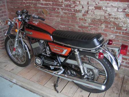
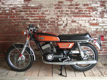
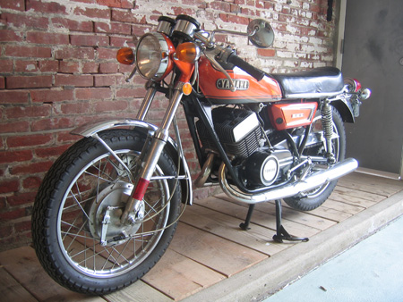
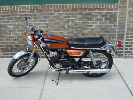
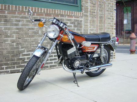
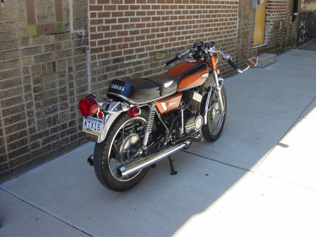
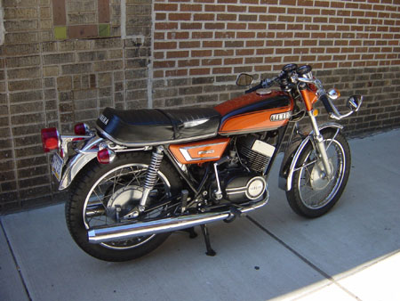
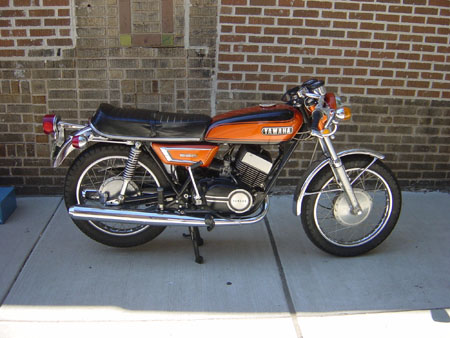
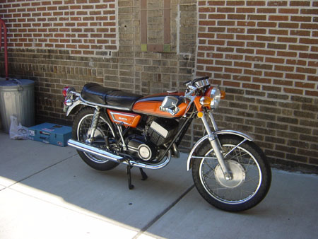
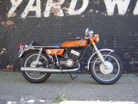
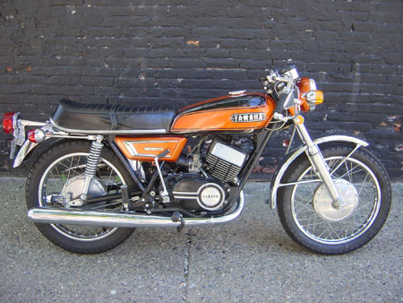
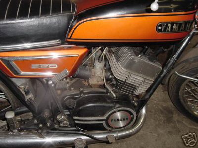
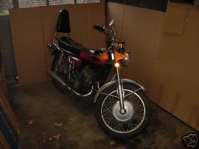
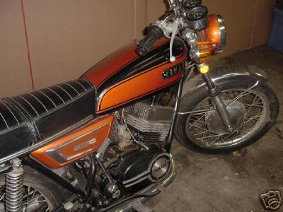
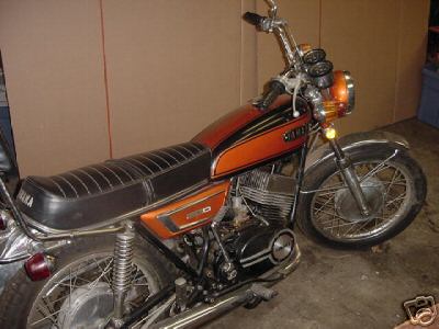
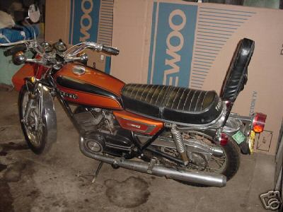
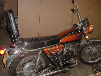
First off I'd like to compliment you on your fantastic looking R5, I hope mine can some day look that good as I am in the process of restoring it right now. I just had some questions that you may be able to answer for me regarding the points and condensors, Would you happen to know the point gap and its timing as well as the gap for the floats? If you have this information it would be greatly appreciated, or if you have any questions go ahead and let me know. Thank you very much.
This directly from the original Yamaha DS7/R5C/RD250(A)/RD350(A) Combined Service Manual (1973) that I was lucky enough to get with the purchase of the bike:
Timing should be checked anytime the points are re-gapped.
Tools necessary:
- dial gauge
- dial gauge adapter
- conductivity test lamp or Yamaha Point Checker
- point wrench
- flathead screwdriver
- 12mm wrench
1) Install a dial gauge adapter in the plug hole on the cylinder head, then install the gauge. Set the indicator to zero when the piston is at top dead center (TDC). Rotate the crankshaft against the normal direction of rotation to 2mm BTDC.
2) Set the point gap at 0.3-0.4mm (0.012-0.016") by moving the breaker plate. When adjusting ignition timing for the left-hand cylinder, adjust the point of the LH terminal (orange), while for the right-hand cylinder, adjust the points of the RH terminal (grey).
3) Connect the positive lead of the point checker to the insulated point terminal. Ground the negative lead of the point checker to the engine or chassis.
4) Loosen the breaker plate setting screw, and move the plate to the right or left with a flathead screwdriver until the point checker indicates the points opening at exactly 2mm BTDC. Do not fully loosen the screw, because the breaker plate tends to move when the screw is retightened. Turning the breaker plate in the normal rotating direction will retard the ignition timing, while turning in reverse direction will advance the timing.
5) Finally, tighten all screws, rotate the crankshaft against the normal, running direction until the dial gauge indicates 2.5mm BTDC. Then slowly turn the crankshaft in the normal running direction. The point checker should just swing into the green at 2mm BTDC, indicating the points are opening causing ignition.
6) For best performance each cylinder's specifications should be nearly identical. Point gap (L&R) should be identical and timing should be within 0.05-0.10mm. Timing on any one cylinder, besides being in balance, must be +/- 0.1mm of 2mm BTDC.
As for the gap for the floats, they should be set to 15mm.
Hope that helps!
Labels: Reader Mail, Technical
This entry was posted
on Thursday, June 16, 2005 at 11:31 AM.
You can skip to the end and leave a response.
![]()
![]()


» Post a Comment